
How the item Engineeringtool is making not only design work, but also the coordination process, much easier.
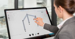
Digital Engineering, with software such as the item Engineeringtool, has made design work much more straightforward. You can save a lot of time by using this online tool, which features rules-based 3D design with drag-and-drop controls, an integrated plausibility check and the automatic placement of machining steps and fasteners. However, the increase in efficiency is not restricted to the design work itself – the tool also specifically improves collaboration between project team members, thanks to various key factors, including direct access via a web browser and a globally unique article number that provides a practical solution for sharing projects. In our interview, Christian Thiel, item expert in digitalisation and design, explains exactly how the free design software improves team work.

How digital is Europe’s mechanical engineering sector?
An enlightening comparison of European countries and information directly from those in the know – take advantage of insights into the digital transformation of mechanical engineering from 295 decision-makers in the engineering field.
GET YOUR COPY NOW!
Which factors normally make coordination difficult in design projects?
If all the members of a project team have a CAD program, exchanging data can prove problematic. This might be because one team member’s FTP tool isn’t working, for example, or because access is denied. What’s more, different versions of the same software are often in use, which can cause compatibility issues. It can sometimes also be the case that partners don’t have special software and so need a 2D PDF drawing. This creates more work. Even if a complex CAD design has already been created in 3D, this can unfortunately not be opened by partners who don’t have the relevant software.
In terms of actual communication, the various people involved speak to each other, but time and again, misunderstandings arise because each person has their own perspective – and these perspectives can vary widely. For example, the CAD designers focus on their CAD system and all the technical details, whereas the purchasing staff are interested in the comparability of prices. The management team, for its part, is interested in information from all the different segments.
So how does the item Engineeringtool help resolve these issues?
For one thing, the item Engineeringtool is in the cloud, which means you don’t need any specific hardware or software to use it. All you need is a device with internet access and a browser. Since it all runs on the basis of WebGL technology, which is supported by all standard browsers, you don’t need to install anything extra, either.
Thanks to the Projectviewer and unique Cx article number, everybody involved can access the project.
Central to coordination is the Projectviewer associated with the item Engineeringtool. It’s a bit like a scaled-down version of the item Engineeringtool – you don’t design projects with it, but you can view them. This software is therefore not aimed solely at design engineers, but instead at everybody involved in the project. To view a particular design in the Projectviewer, all you need is the globally unique Cx article number. Every item Engineeringtool project that has been placed in the shopping cart has a Cx number.
Projectviewer – the basis for optimal coordination
So all you have to do is send this Cx article number to those involved in the project?
That’s right. To view the design, the project team members simply need the link to the Projectviewer and the Cx article number. The Projectviewer offers a whole host of functions. Whether you want to view the documentation, use an animated 3D assembly guide, access CAD data, open projects to edit them or place projects in the shopping cart, you can do all these things in the Projectviewer.
If you have any questions about a component, you can also access additional information in the properties’ window by clicking an information button. The component dimensions are also displayed. All in all, the Projectviewer gives everybody involved in the project quick, straightforward access to the information that matters to them. Everybody can extract what they need – but everything is on the same foundation.
Design software – bridging the gap between the digital and real worlds
What’s the situation regarding the link between the digital world and the real one?
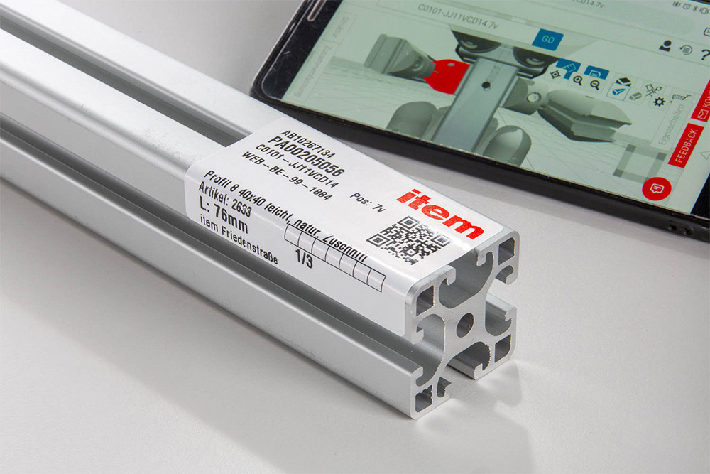
When developing our design software, it was really important to us that we didn’t end up with a solution that only worked well online. When it comes to customer service at item, we always take a holistic approach. We therefore wanted to link the two worlds. As an example, fitters working on site specifically benefit from our approach. Every machined item component has a label with a QR code on it. All you need to do is scan this code with your smartphone or tablet and the Projectviewer opens immediately. You then see where you need to fit the relevant component in a realistic 3D environment. Since the QR code is also on the cover page of the project documentation, you can also scan it with your device there.
The position number also speeds up the assembly work. This is a unique number that is assigned to every component in a design (e.g. a cut-to-size profile). As the position number is printed on the label of every component, all the components can be precisely matched – not only in the parts list, but also in the assembly guide and other documentation.
The recommended assembly sequence is presented in an animated 3D assembly guide. The assembly of each individual component is shown in an animation. What’s more, you can watch each step as often as you like.
There is also another function that particularly lends itself to use on a mobile device. The recommended assembly sequence is presented in an animated 3D assembly guide. The reason for this is that the fasteners mean you need a specific “assembly strategy”. Our software can recommend such a strategy, which makes the fitter’s job much easier.
Even if it’s just a case of double-checking something or getting ready to do a particular job, fitters undoubtedly benefit from the 3D assembly guide. The assembly of each individual component is shown in an animation. What’s more, you can watch each step as often as you like. The whole thing is really easy to follow.
The term “digital twin” has already been taken. However, could it be said that this design software is also moving in the same direction?
Yes – although obviously not in the same sense that we speak about a machine’s digital twin, complete with predictive maintenance and so on. However, we are digitalising item products. Their digital versions are therefore available in the item Engineeringtool and Projectviewer, and in our other online tools. Since the technical properties are also taken into account here, the software can also recommend an assembly sequence, which proves very useful directly in the production area. Thanks to this digitalisation, our customers benefit from a much faster design process.
Are you interested in digitalisation and what the future holds for mechanical engineering? Then we have something that’s right up your street! Simply subscribe to the item blog by completing the box at the top right.